The history of shotcrete
Since its conception in the early 1900s, shotcrete application has developed to become one of the most critical ground supporting techniques for underground excavations. The technology has evolved from manual nozzle handling to computer guided, hydraulically controlled boom-mounted nozzles. By controlling variables in the shotcreting application, the layer of sprayed concrete can be optimally designed to meet the in-situ geotechnical constraints. In some scenarios, shotcrete will be designed to flex with the squeezing rock, whilst in others, it may simply act as a barrier to protect from rock bursts.
Understanding how the shotcrete will react in different conditions allows operators to apply the right amount of material. Shotcrete thickness is paramount when applying shotcrete, therefore it must be monitored during application using the safest and most reliable method. The aim of this article is to demonstrate how the SR-50 system, developed by GeoSLAM, is suitable for near real-time shotcrete application quality assurance and quality control (QA/QC).
Shotcrete – The modern method with failing processes
The Sika Sprayed Concrete Handbook (1) states that the only method for accurately calculating initial strength is by measuring thickness. Current methods rely on operators endangering themselves to un-secured shotcrete in order to manually collect thickness readings. A total of 5% of all tunneling injuries can be attributed to the shotcreting process in tunneling (2). Industry professionals recognise the need to balance the provision of a safe working environment for its operators with the demand for increased production rates, accurately measured and documented shotcrete thickness.
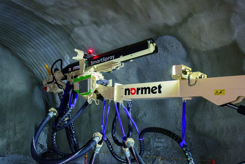
In 2016 GeoSLAM developed the SR-50 system deployed throughout the Jetcrete Australia fleet. The technology has now been licensed to Normet Oy who have adopted the technology as SmartScan.
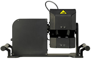
SR-50 System
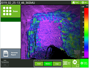
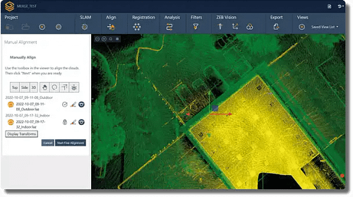
SR-50 Software
Interface
The system provides the operator with near real-time results displaying shotcrete thickness after each application cycle with a single button press. A colour-coded map of the spray area allows the operator to identify regions of concern easily and accurately. Once the operator is satisfied that the sprayed thickness complies to site criteria an electronic report is automatically created. This report documents the application cycle, providing the average applied thickness, total volume of shotcrete applied to the surface and the final thickness map that can be used for quality assurance. All data is stored on the system for further analysis and archiving. Without exposing the operator to dangerous conditions, the system can act as a training tool for novice operators, as well as aiding experienced operators to spray to the desired profile thickness, thus minimising overspray.
Analysis of data collected from sites using the SR-50, showed an approximate 20% reduction in overall concrete usage. This means that an average single sprayer operation can reach a return of investment within 2-3 months, have improved safety, and expedite the shotcrete application process.
The system created by GeoSLAM now achieves an accuracy of less than 5mm. This measured accuracy and reliability of measurement now enables the large-scale use of the technology on multiple sites.
The need to modernise
Traditional methods for measuring shotcrete thickness are based on invasive in-situ sampling at discrete points. Samples are taken either, when the shotcrete is freshly applied, e.g., Fibercrete Depth Indicators (FDI’s) or once the shotcrete has fully hardened, e.g. ASTM C174 drill core test. In both cases these methods have been shown to be unreliable and disruptive to the work cycle.
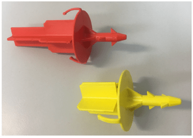
Fibrecrete Depth Indicators (FDI)
FDI’s are used by inserting “shotcrete stamps” into freshly applied shotcrete using the boom of the spraying rig. An investigation carried out at Olympic Dam in 2018 concluded that FDI’s were incredibly disruptive to the operation as well as poor measurement technique to represent the whole heading (3). For a typical profile heading with a cut length of 4.0m, the surface area sprayed was approximately 55m2. 20 probe sites were sampled, resulting in a sample area of approximately 0.05m2, or just 0.0009% of the sprayed surface.
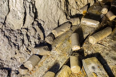
Drill Core Tests
Where drill core tests are taken most sites typically only manage to measure samples to the nearest 10mm, and again there is an element of bias towards where these drilled samples are taken from along the profile of worksite. Aside from an unsatisfactory sample size and potential for bias, the above methods either have the potential to damage the spray rig boom or are conducted hours after spraying, so any issues are not resolved at the time of application which result in time delays and extra costs.
There is an increasing trend in tenders and contracts throughout the shotcreting industry, requiring that shotcrete thickness be accurately measured and documented across the whole sprayed surface. Therefore, new, and novel methods must be used to meet the contractual obligations whilst minimising the disruption to the work cycle. The use of Laser Scanning technologies can meet these demands by providing non-invasive measurements at the time of application; sample points that can run in to the hundreds of thousands, overcoming sample bias; all taken in a handful of minutes immediately after the application meaning that any remedial action is taken immediately.
Laser Scanning: Accuracy benchmarks
Terrestrial Laser Scanners (TLS) and Scanning Total Stations (STS) systems are based on laser technology and are commonly used across numerous surveying sectors where accurate range measurements are required. Typical systems have accuracies that range from sub-mm to several mm’s depending on the underlying technology and cost. However, in the underground environment these technologies tend to be extremely expensive, complex to use, often requiring specialist training, and can require time-consuming processing in an office environment to produce results. The SR-50, although based on laser scanning technology was specifically designed for the shotcreting industry to be simple to use, automated, cost effective and accurate.
To evaluate the accuracy of the system a rigorous approach was developed. The assessment criteria relied on the use of a TLS (Riegl VZ-400) that was deployed in a controlled environment. The TLS was chosen on the premise that to assess the accuracy of the SR-50, the reference data must of greater accuracy than the test data. The ability to control any changes in the environment was paramount to avoiding ambiguities in the results.
An artificial tunnel environment was constructed with cross-sectional dimensions similar to those in the mine tunneling environment. After an initial base scan of the environment, using the TLS and SR-50 a series of control-panels of known thickness (verified using vernier callipers) were introduced at varying positions in the tunnel. After each control-panel was introduced, changemaps were calculated from SR-50 and the TLS data. Thicknesses of 8, 13, 18 and 30mm were used.
The Results
The first assessment of the SR-50 system was to compare comparison results of the test environment with no change against the results using the TLS. Since, there was no physical change to the environment this provided an indication of the repeatability of the system. This assessment was then repeated by placing 8mm, 13, 18 and 30mm boards into the scene and measuring the average thicknesses using the SR-50 and TLS data.
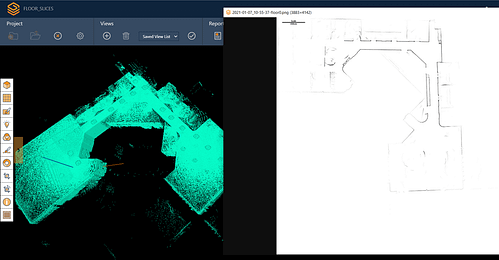
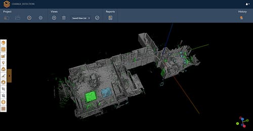
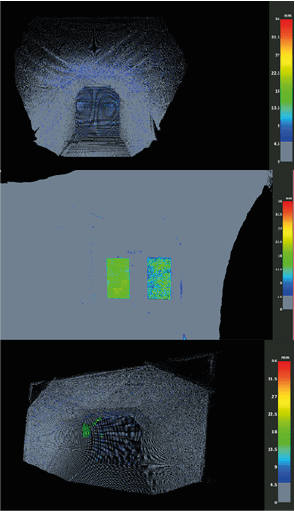
The top image shows the comparison map derived from the SR-50 when no change was made to the environment. The middle shows a comparison of the computed changemap from the TLS control-panel (LHS) and the panel measured by the SR-50 (RHS), both for a 13mm control-panel. The figure clearly shows that the SR-50 gives comparable results to the TLS. The changemap for the TLS gives a more consistent result due to the much higher point density. However, the measured average change across the panels are the same. Control-panels were also attached to the sides and shoulders of the test area and an example changemap is shown in the bottom image.
| Board Thickness (mm) | 0 | 8 | 13 | 18 |
|---|---|---|---|---|
| Smartscan Selection Mode Difference (mm) | 0 | 0 | 0 | 0 |
| Third Party Difference (mm) | 0 | 1 | 1 | 1 |
The above table provides results for the comparison between the average thickness of the control-panels measured using the TLS and SR-50. To assess the accuracy of the automated changemaps created in the SR-50 software, the raw data was exported and thickness maps were calculated in a 3rd party software. The results show good agreement with the on-board solution available at the time of spraying.
Conclusion
By using laser technology and scanning the working area before and after shotcrete application, shotcrete thickness is automatically calculated across the complete working area in near real-time.
To provide an initial assessment of system accuracy, a series of measurements were undertaken in a man-made, controlled area. A series of control-panels of known thickness were introduced into the environment and thickness maps calculated by the SR-50 were compared to maps created using a Terrestrial Laser Scanner of much higher specification. Additionally, the results automatically created by the system were compared against results created manually in a 3rd party software package.
The results showed that thickness maps created using the SR-50 system were comparable to a TLS system. Average control-panel thickness was typically within 1-2mm between the two systems. The investigation shows that the SR-50 is accurate and reliable enough for the shotcreting industry. When comparing to the inaccurate in-situ measuring the industry has previously adopted (such as the ASTM C174 drill core test), the SR-50 can provide reliable results across the whole sprayed face in near-real time. The system is able to:

Provide an accurate thickness report every time a spray is required

Drastically reduce shotcrete wastage by helping the spray application process in achieving its desired thickness in a single attempt

Ensure geological ground control is achieved and upheld during the full shotcreting operation

Help nozzle-persons gain experience in spraying by providing near-real time thickness results.
As shotcreting becomes more common in mining and infrastructure projects around the world, the industry needs to evolve to accept the need for strong QA/QC methods and reporting in near-real time.
References
- Sika Services AG. (2020). Sika Concrete Handbook. Available: https://www.sika.com/content/dam/dms/corporate/t/glo-sika-concrete-handbook.pdf. Last accessed September 2020
- Kikkawa N, Itoh K, Hori T, Toyosawa Y, Orense RP. Analysis of labour accidents in tunnel construction and introduction of prevention measures. Ind Health. 2015;53(6):517-521. doi:10.2486/indhealth.2014-02
- Unpublished site report: Olympic Dam, BHP, 2018.